Where can I find repair parts?
What parts are common/different between the models and years?
What are common problems with the 924/931?
How do I set the valve and ignition timing?
How do I adjust the valve clearance?
Where are the electrical ground points?
How do I bridge the fuel pump relay, and why?
What relay and fuse is for what?
How do I adjust the fuel mixture?
Where are the option codes listed and what do they mean?
What is my paint color?
Tell me about the CIS fuel system.
Where can I find maintenance information?
I think the best source of information on the web is at (http://www.924Board.org). It is the discussion forum of the official PCNA 924 web site. The members there are the foremost authorities with regard to information specific to the 924/931 that exists on the web.
The maintenance manual published by Haynes and is probably the best available, outside the actual factory manuals. There is a Russian web site that has the Haynes manual online. That web site has the index in Russian/Cyrllic, but the actual chapters are in English...you will just have to fumble through the contents to find what you are looking for. Chilton's also publishes a manual on the 294/931/928, but it is not nearly as detailed as Haynes.
The factory maintenance manuals are very desirable, can be found in hard-copy and also on CD. They sometimes come up for sale on e-Bay, but you can purchase them from a number of sources. The 924 manuals come in four volumes, with information specific to the 931 in a fifth volume. Another indispensable resource is what is referred to as "PET" or the "PET CD". It is a computer program that has exploded diagrams and all the part number information needed to order parts from the dealership. Using it you can figure out which parts are interchangeable from year to year. It also has all the option codes, vehicle, engine and transmission serial number information.
Back to top
Where can I find repair parts?
Of course there is the dealership...and sometimes this is the only place you will find what you are looking for. Since the car was originally a Porsche/Audi/VW project, many of the parts in the 924/931 can be found where you would find Audi and VW parts. More often than not though, you will have your best luck using some on-line sources. I put together a page with some links to vendors who have many of the things that we 924/931 owners commonly need when restoring or maintaining our cars. This list of sources is an ever-changing resource. My suggestion is to shop around, and remember that shipping charges can easily offset any savings you find at a particular retailer.
An indispensable resource when dealing with repair parts is what is referred to as "PET" or the "PET CD". It is a computer program that has exploded diagrams and all the part number information needed to order parts from the dealership. Using it you can figure out which parts are interchangeable from year to year. It also has all the option codes, vehicle, engine and transmission serial number information.
Back to top
What parts are common/different between the models and years?
There are a host of minor differences between the different year model 924's and the different year model 931's. I'm not an authority on those differences, so I will refer you to the http://www.924.org web site and it's discussion forum at http://www.924Board.org. Use the search function and you'll turn up tons of information.
The 924S is essentially a 944 with a 924 body on it. The "S" uses a 2.5 liter powerplant, and some suspension refinements to set it apart from the earlier model 924 cars.
The turbocharged 924, the 931, differs from the normally aspirated model in that it has a turbocharger, a different cylinder head, manifolds and pistons, it uses different fuel injection components, a different transmission and drive tube/shaft. There are a lot of other things that set the 931 apart from the 924, but these are the major points.
Differences between the US market cars and the Rest of World (ROW) cars is that they have different pistons, and the US cars have
Attempting to convert a 924 into a 931 is a project that will cost way more money than buying a 931 to begin with.
What are common problems with the 924/931?
How do I set the valve and ignition timing?
Setting the valve timing:
How do I adjust the valve clearance?
With the engine at operating temperature (80oC/176oF oil temp), remove the valve cover. By hand, rotate the crankshaft so that both valves of a particular cylinder are closed (lobes are both pointing up). Using a feeler gauger, measure the distance between the top of the valve tappet and the cam lobe. The proper clearance is: Intake valve, 0.2mm, Exhaust valve, 0.45mm. Turn the adjusting screw one full revolution (clockwise reduces the distance between the tappet and the cam, counterclockwise increases the distance) and re-measure. One full revolution will change the clearance by 0.05mm.
Take extra caution that the adjusting screw is not backed out so far that it's head protrudes from the hole in the side of the tappet, nor is it screwed in so far that it's toe sticks out of the other end. This is what the special tool is for, it has a built-in gauge telling you whether or not the adjustment is "safe" for that particular adjusting screw. The screw should have [however many] threads engaged in the tappet in order to support the strain placed on it by pushing down in the valve stem.
Where are the electrical ground points?
How do I bridge the fuel pump relay, and why?
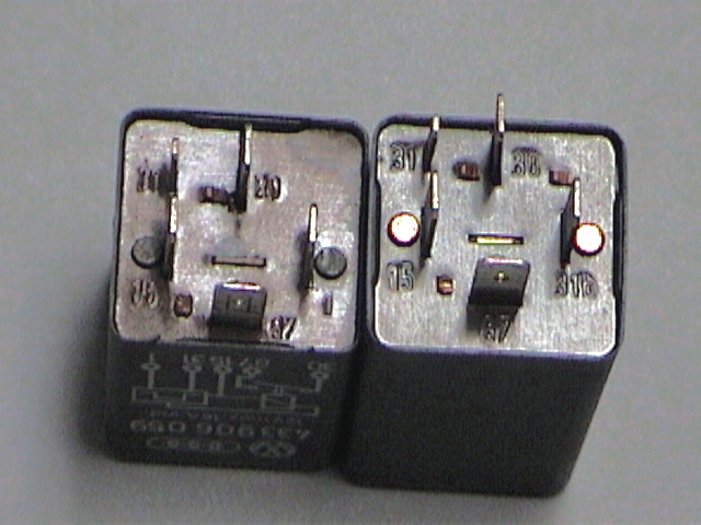
You bridge the relay by removing the relay from it's seat (top row of relays, second from left) and putting a short length of wire with male spade connectors on both ends into two of the numbered pin slots. To have the pumps run only with the key turned to the "ON" position, use the slots marked 15 & 87, or for continuous power bypassing the ignition switch, use 30 & 87. The relay seat and the base of the relay itself have the numbers on them.
What relay and fuse is for what?
How do I adjust the fuel mixture?
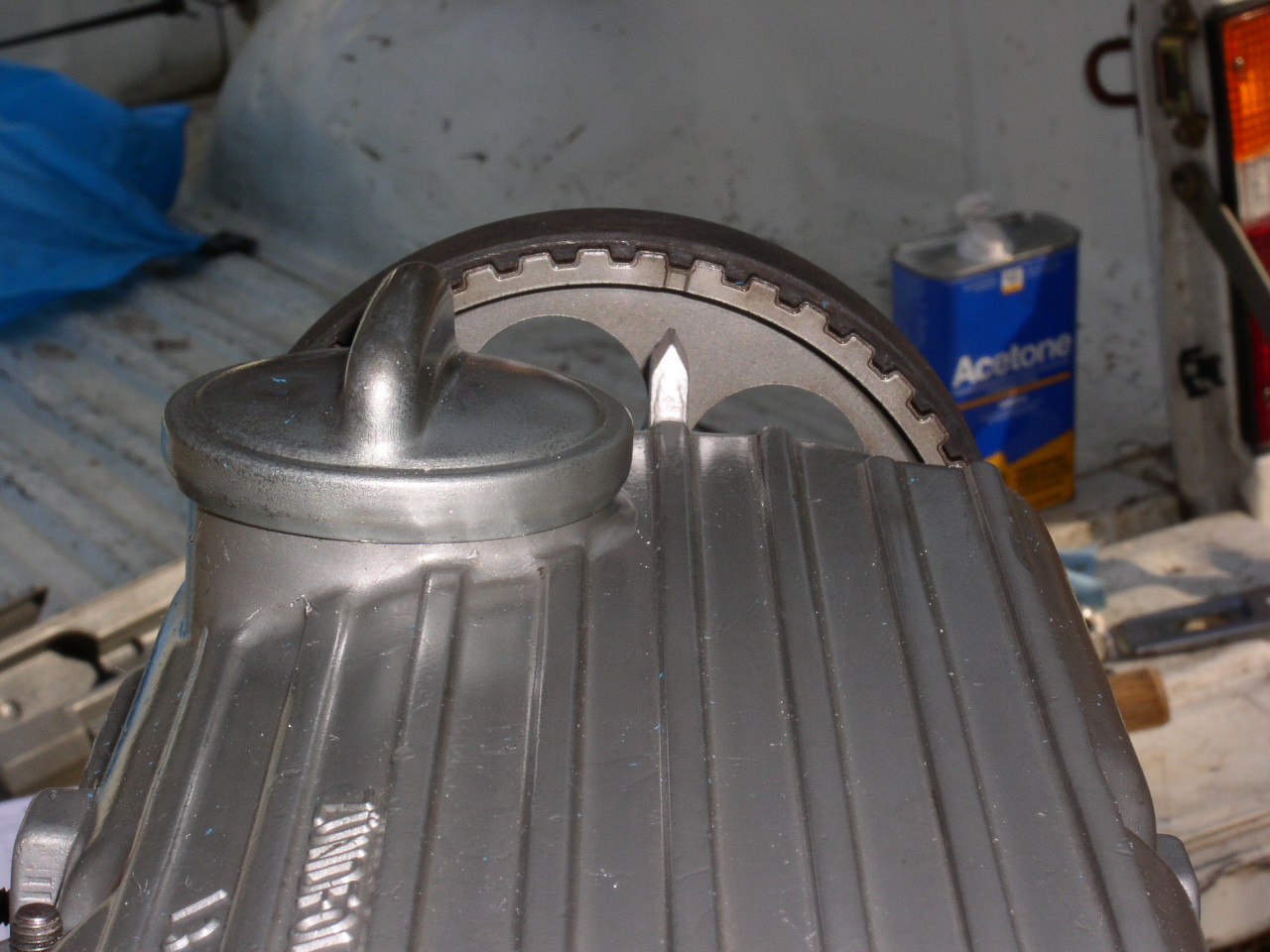
The mixture is adjusted by turning a set-screw (3mm Allen head) that is down inside the airflow metering box (that thing with the round plate on it, attached to the fuel distributor). There is a hole on top of the box, between the actual fuel distributor and the boot that covers the metering plate that gives access to the adjustment screw.
The factory manual gives the following instructions for a "baseline" mixture setting after ensuring that the metering plate is correctly adjusted
Where are the option codes listed and what do they mean?
There are a number of "decoders" on the web that will do a better job of telling you the codes than I could list here. Click this link for one such option decoder. Another option list can be found here.
What is my paint color?
Answering the question of what the actual color is, is another question more easily answered by referring you to the 924 Discussion Board. Click here for a post with the paint code list.
Tell me about the CIS fuel system.
With or without the added-on electronics, the systems are very similar. Fuel is delivered under high pressure to the fuel distributor, where it is metered and sent to the injectors. The system continuously squirts fuel into the cylinder head, just above the intake valves. The injection is not done in sequence, nor is it pulsed in time with an individual piston.
The system is actually quite simple in operation, yet at the same time it is fairly complex to get everything working just right. Once set, it is a very reliable setup, provided it is used frequently. These cars do not like to sit for long periods of time. Inactivity will lead to the fuel system giving you problems.
The main components of the CIS system are:
Back to top
Before directly answering the question I want to remind you that even the newest 924 is approaching 20 years of age, and the oldest ones are nearly 30. Just about any car of that age that has been used consistently for that long is going to have parts that wear out, break or otherwise need replacement. The list below outlines some things that a prospective buyer should look at or at least keep in mind, in that they could need attention within the first couple years of ownership, depending on whether or not they have been replaced recently.
Back to top
Setting the valve timing and setting the ignition timing are two different but inter-related tasks. Both must be set properly for the engine to perform correctly. Having proper valve timing ensures that the valves open and close properly, in relation to when the pistons are at a particular position. The 931 has what is known as an "interference engine", which means that the valves can collide with the pistons if the valve timing is not set correctly. The ignition timing is set so that the spark occurs at the proper time in relation to the position of the piston and valves. On earlier cars the ignition timing is manually set, while on later cars that are equipped with the digital ignition timing, the ignition timing is controlled by a computer which gets input from some sensors.
Now, set the ignition timing
 Align #1 cylinder at Top Dead Center
- or -
Back to top
 Loosen distributor hold-down bracket
The valve clearances are set by turning an adjusting screw found on the sides of the valve tappets. The screws have a 3mm allen head, and should really be adjusted with a special tool to ensure that the screw is neither too far in or out. The screws themselves have an angled flat face on one side, so that when you turn the screw one way or another, it adjusts the valve clearance. These special screws come in different "sizes" so that different screws provide a different minimum and maximum adjusting range. If the existing screw doesn't "adjust out" enough, you have to replace the screw with the next size.
Back to top
Every electrical device needs a positive electrical source and a ground, so all of them won't be listed here. But there are several main ground points that should be checked and cleaned to ensure the gremlins are kept at bay. Click here for photos of ground points listed below.
Back to top
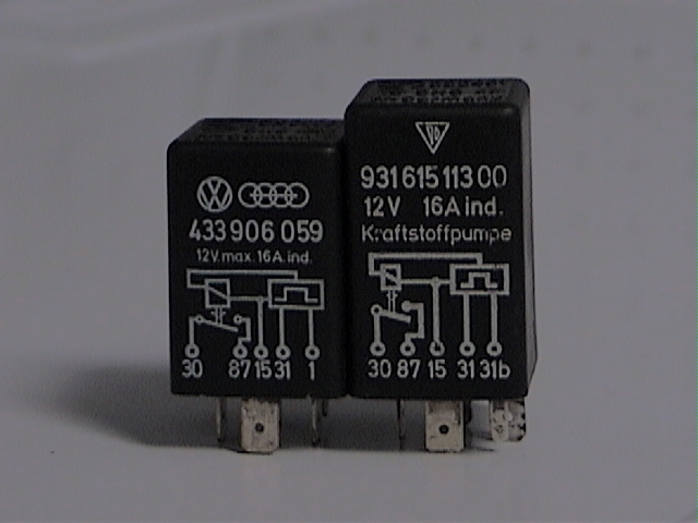 The fuel pumps get their electricity through the fuel pump relay. The relay functions by sending power to the pumps in two conditions: 1)when the key is initially turned to the "ON" position, and 2)when the engine is running. Initally, when you turn the key to the "ON" position, the pumps are given power for a couple of seconds. This is done to pressurize the system when preparing to start the car. If after the initial couple of seconds the car doesn't start, the relay opens the circuit and cuts power to the pumps. If the engine starts, the relay gets a signal from the coil and the relay continues to pass power to the pumps. If the engine stops, power to the pumps is cut. This is a safey feature, and I do not recommend operating the car with the relay bridged. The photo on the right shows a 924 (and ROW 931) relay on the left, and a US 931 relay on the right. The difference is that the US 931 relay also has a function of limiting the engine's RPM. The ROW 931 has it's rev-limiting function built into the distributor rotor.
 In order to perform some tests on the fuel system, it is necessary to bridge the fuel pump relay, bypassing its function and allowing the pumps to run continuously without the engine running. When you bridge the relay, you can do it so the pumps are given 12v power all the time, or they are given power only when the ignition key is turned to the "ON" position (my preference).
Back to top
The fuses and relays changed slightly during production, and I don't know exactly which year. Also, there was some variation between US and ROW models. The photo at right shows the 15 main fuses and the bottom row of relays. White fuses are 8-Amp, Pink/Red=16-Amp, Blue=25-Amp
Listed below is how my car is set up:
There is also a "free hanging" relay for the electric windows, found clipped to the air vent opening down by the drivers feet.
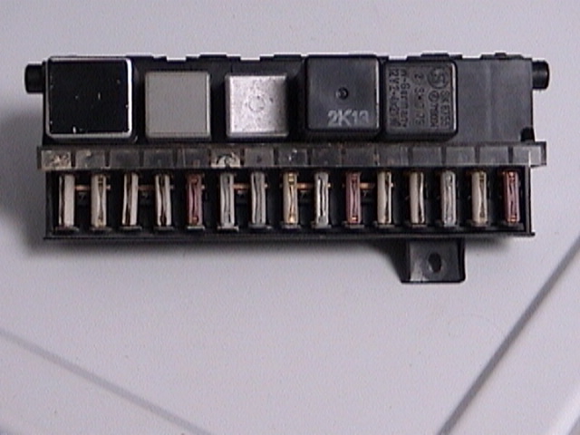 Main fuse panel (Pictured at right)
Back to top
Adjusting the fuel mixture is probably the last thing you should try in attempting to sort out any kind of fuel delivery problem or tune-up issue. Adjusting the mixture so the car seems to run properly can mask an underlying problem.
Back to top
The list of options is found on a sticker back back by the spare tire well. They should also be listed in one of the owner's manuals that came with the car (if you are lucky enough to have the original documents).
Back to top
 The sticker telling you what the paint color of your car is, is found in the engine compartment on the left side, up by the windshield wiper motor. Click on the photo to the right and it will show you where to look.
Back to top
The CIS fuel injection system found on the 924 & 931 is the Bosch K-Jetronic Continuous Injection System. Although the trade name implies an electronic control, in fact the injection system is mechanical. My car is a European version and does not have the "Lambda" electronics that help with fuel management. The later Lambda-equipped versions have an on-board computer that adjusts ignition timing and other fuel management functions to help with emissions controls, but the fuel delivery is still mechanical.
Back to top
The main fuel pump in the 924/931 is of rotary design, and looks like an alumninum cylinder with a nipple on each end. The pump supplies fuel at a pressure around 80-90 psi, at a rate of 1.5 liters a minute. Earlier cars had a single pump external to the fuel tank, later cars have a pump inside the fuel tank in addition to the external one.
The accumulator acts as a small pressure-saving device that assists the CIS system when starting with the engine warm. The device is a small metal cylinder with an inlet and an outlet on the top, and it has a rubber bladder inside. When the fuel is pumped, the pressure inflates the accumulataor's bladder. A check valve between the pump and the accumulator prevents backflow when the pump is turned off. Thus, when you restart the engine after a brief shut-down, the fuel system already has some pressure in it.
This device meters and distributes the fuel to all the fuel injectors, the control pressure regulator and the cold-start valve. Inside the distributor is a plunger that when raised and lowered, allows fuel to pass to the individual injectors. The farther the plunger is moved, the more fuel it allows to pass.
This is the box the fuel distributor is bolted to and has the large rubber boot leading to the air intake. Inside the metering unit is a circular plate that moves up and down in the airstream that goes into the engine. There is a lever attached to the circular plate that acts on the plunger inside the fuel distributor. As more air moves past the plate, the farther the plate deflects, the metering plunger is moved more, and more fuel is allowed to go to the injectors.
Also known as the "Warm Up Regulator", or "WUR". It works in conjunction with the fuel distributor to help precisely govern the fuel mixture as the engine warms up because it needs more fuel when cold than it does when it is warmed up. The fuel distributor has a fuel circuit on it that has pressurized fuel acting on top of the metering plunger. If the pressure in this circuit is high, then it takes more force to move the metering plunger to the open position. Likewise, when less pressure is on the plunger, moving it takes less force. The WUR changes the control pressure that acts on top of the plunger, gradually increasing the control pressure as the engine warms. So, with lower control pressure the airflow metering plate within the airbox will move a greater distance given a volume of air than it would with that same volume and a higher control pressure.
These devices screw into the cylinder head just upstream of the intake valves. If supplied with fuel under enough pressure they will open up and spray a fine mist of fuel into the air as it flows into the engine.
This device comes into play during "cold" engine startup and initial warm up, with it's primary function being to assist idle stabilization. Inside the device is a rotating plate with a hole in it. When cold the hole is aligned in such a way that it allows more air into the engine, bypassing the throttle body. As the AAV and engine warms up, the plate gradually rotates and the hole is closed off, resulting in less air bypassing the throttle body, lowering the idle speed.
This switch controls the electrical ground to the Cold Start Valve. It will provide a ground if it is cold, and/or power to the switch is applied for fewer than about 10 seconds. If powered for a longer period, or if the engine is warm, then it opens the circuit preventing the cold start valve from injecting.
This is a fifth fuel injector that is electrically opened when the key is turned to the "Start" position, and if the engine is cold. It's power circuit is grounded through the thermo-time switch, so that when the engine is warm it will not fire when the key is turned.